In this article, I will introduce you to basic electronics and provide you a basic understanding of electronics principles that you will need to use. In my previous tutorial article What is Electricity? you learned how electricity works.
Electronic devices for example include cell phones, computers, radios, and digital cameras. Electronic devices such as cell phones do many things, like taking pictures, playing music, making a phone call, browsing the internet, and many other things. Electronic devices such as a light bulb convert electric current to light which we use in our homes to see.
Back to Basics
The electronics field can be very difficult due to abstract theory, new electronics devices become more difficult to repair or understand how they work due to complex circuits. One must go back and understand basic concepts, such as resistance, current, voltage, and power. These concepts at first can be difficult to understand for example we can’t “see” current flowing through a wire or a conductor, but we can measure current using a multimeter or oscilloscope. In my previous article Voltage, Current, and Resistance I introduced you to the basic concept of voltage, current, and resistance and their relationships.
Circuits
Electricity (Current) is the flow of electrons through a conductive path like a wire. A circuit is a path that electricity flows along.
Open circuit – the path is broken and no current flows.
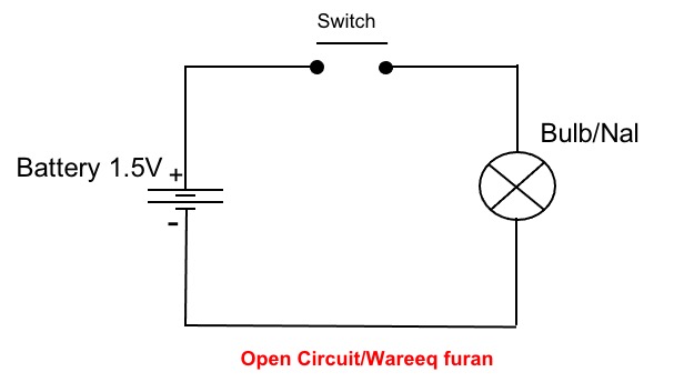
Close circuit– the path is complete and the current flows.
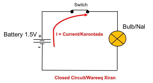
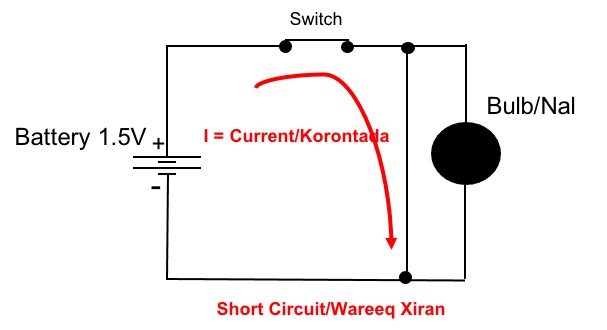
Short circuit – The path of the current is wrong.
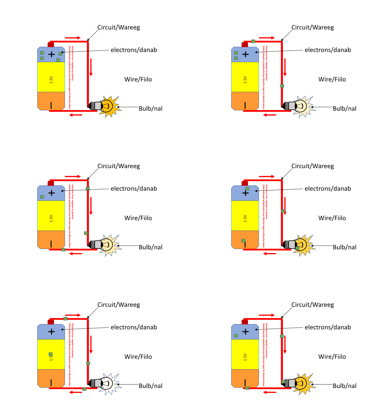
The animation below shows an example of a circuit. It starts at a power source, like a battery, and flows through a wire (conductor) to a light bulb. The animation below shows a simple circuit that contains a 1.5V battery, a wire (conductor), and a light bulb. The negative terminal of the battery pushes electrons towards the positive terminal which attracts the electrons, thus completing the circuit. This is the starting point of understanding how electronics work.
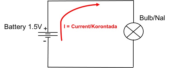
The schematic diagram below shows a simple circuit.
In Electronics current and voltage in a circuit is very important to keep track and control their behavior in a circuit.
Electric current (I) is the movement of electric charge (Charge can be Electrons or Protons) in a wire over a period of time. It is measured in Amperes.
Voltage (V) is energy required or work done to move a unit of charge from one point to another. It is measured in Volts.
Resistance (R) is a measure of the opposition to the current flow in a circuit. Resistance is measured in ohms (Ω).
Power (P) is the rate at which work is done and is measured in Watts (W).
Resistor
A resistor (R) is a device used to limit the flow of electric current in a circuit. The animation below shows how the resistor works. Resistors are used in almost all electronic devices to control or reduce the flow of current.
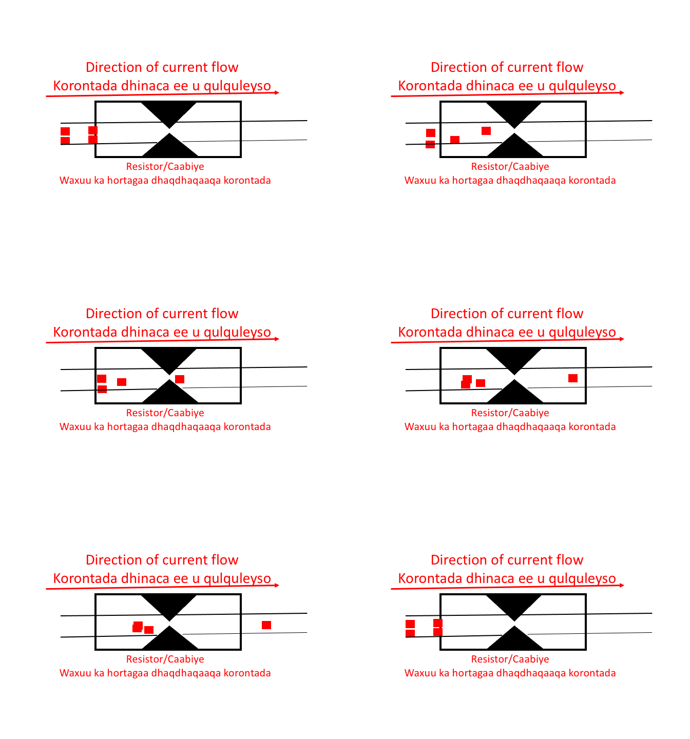
A resistor is a passive component because it consumes power that is dissipated as heat. Most resistors have a fixed value, but there are variable resistors that are called Potentiometers.

The resistor rating determines how much power it can handle without overheating.
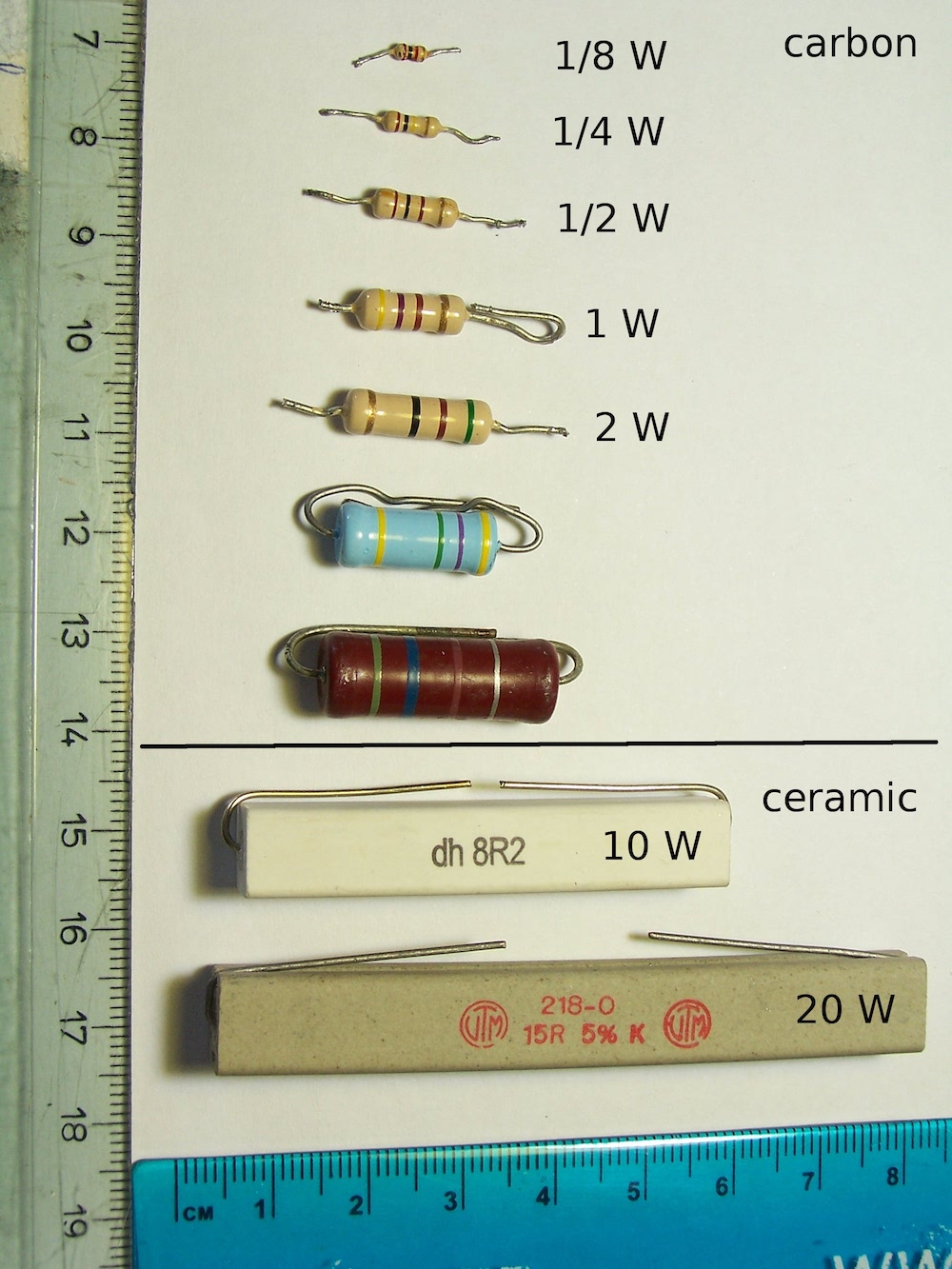
Resistor color code
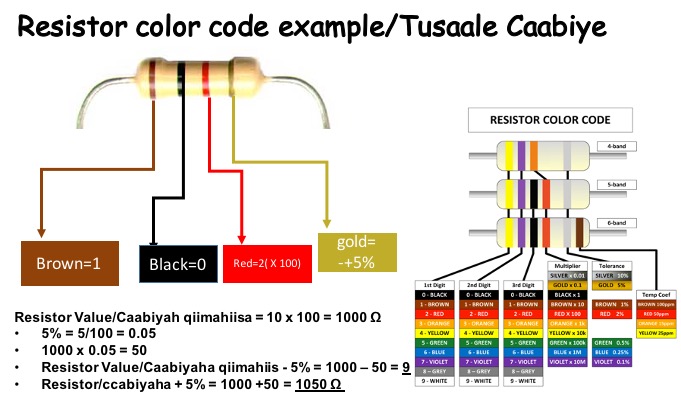
The resistor has a value that tells how strongly it resists current flow, this value is in Ohms (Ω). The color band of the resistor is very important to find the value of the resistor. The example below shows how to read and calculate the value of the resistor.
Ohms Law
Ohm’s law defines the relationship between voltage, current, and resistance. Ohm’s law can be written using Ohm’s Law Triangle (Above picture). Please read the Voltage, Current, and Resistance article to understand more about this relationship.
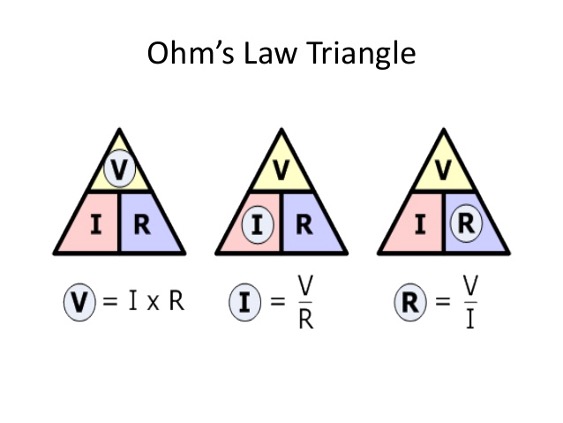
Voltage = Current X Resistance
Current = Voltage / Resistance
Resistance = Voltage/Current
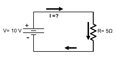
How much current (I) will flow in this circuit if the voltage is 10V, and the resistor is 5Ω?
Current = Voltage / Resistance = 10 V / 5Ω = 2 A (A = Ampere)
Capacitor
Another basic electronic component that you need to know is the capacitor. Capacitors like resistors can be found in almost all electronic devices. Capacitors store electrical energy in the form of electrical charges accumulated on the plates. Capacitors have two parallel conducting plates made mostly Aluminium separated by an insulating material such as glass, air, waxed paper, mica, ceramic, and plastic which oppose current to flow.
If you connect a voltage source to the two capacitor leads (+,-), the capacitor will store this energy, think capacitor as a rechargeable battery.
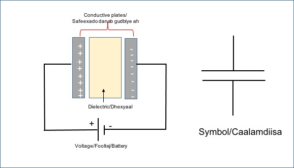
Capacitance (C) is the ability of the capacitor to store energy in the form of an electrical charge, which is measured in Farad, named after Michael Faraday.

Capacitance =Q/V, Q=Charge on the plates, V=Applied Voltage.
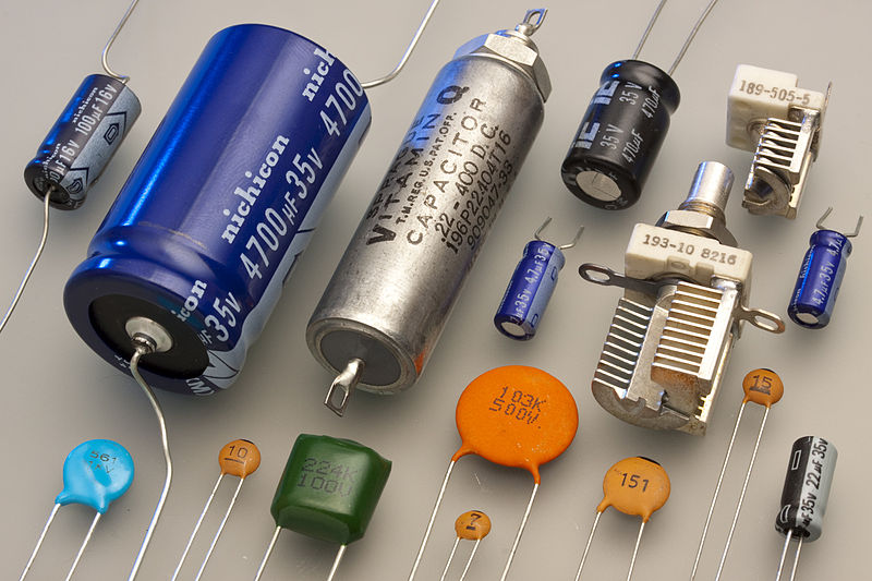
Capacitors are used for many applications such as power supplies, telecommunications, computers, radios, etc..
Inductors
Another Electronic component you need to know and understand how it works is the Inductor. If you take a straight piece of wire and make several loops (coil) you have an inductor. An inductor can also be called a choke, etc.
Inductors store energy in a magnetic field when an electric current flows through it. Inductance is the ability of the inductor to store in the form of magnetic field energy. Inductors oppose any changes of current through them, while the capacitors oppose the changes of voltage across their plates.
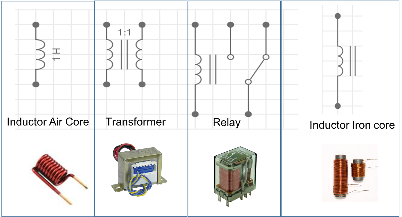
Inductors like resistors and capacitors are used in many areas of electrical and electronic circuits. Inductors are used in transformers (power supplies), filtering, TV, and Radios.
Semiconductors
Semiconductors are used in almost all electronic circuits. Semiconductors are materials whose conductivity lies between conductors and insulators (nonconductors).
Diode
A diode is a semiconductor. Diodes conduct current only in one direction they have what is called a PN junction.
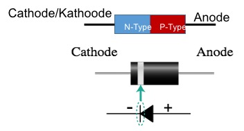
Forward biased and Reverse Biased
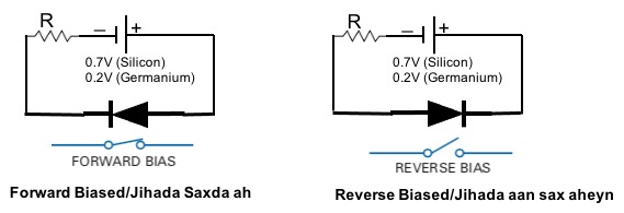
Forward biased
The diagram above shows when the diode operates in forward-biased and reverse-biased. When you connect a voltage of 0.2v (Germanium) or 0.7V (Silicon) across the diode terminals cathode (-) and anode (+) the circuit is complete and electrons can flow.
Reverse Biased
When the diode is reverse biased as shown in the diagram above no current will flow until the voltage across the diode terminal is increased so high that the diode breaks down.
LED
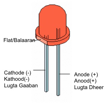
LED (Light Emitting Diode) is also a diode that can emit light when forward biased.
Transistors
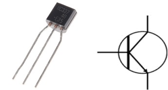
The transistor is also a semiconductor that amplifies electronic signals and also works as a switch. All computers, cell phones, cameras, and almost all electronic devices have transistors in them. It is one of the most important inventions of the 20th century.
MCU (Microcontroller Unit)
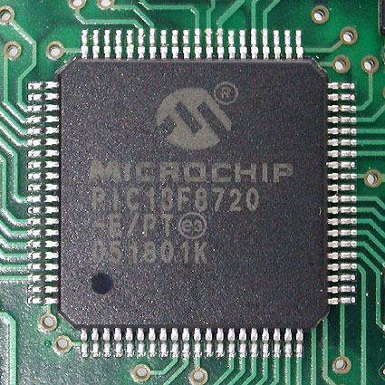
A microcontroller is a type of computer or the brain of most electronic devices, such as cameras, cell phones, and computers. A microcontroller contains one or more central processing units (CPU), memory, and many peripherals such as USB, I2C, etc.
Arduino Uno
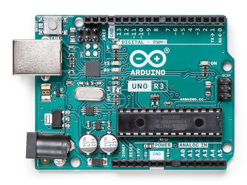
Arduino Uno is a microcontroller board based on the ATmega328P. It has 14 digital input/output pins (of which 6 can be used as PWM outputs), 6 analog inputs, a 16 MHz clock, a USB connection, a power jack, and a reset button.
It is the most popular Microcontroller, is an easy-to-use, open-source microcontroller board, great for beginners and those with limited knowledge of electricity, programming, and electronics.
Schematic Diagram
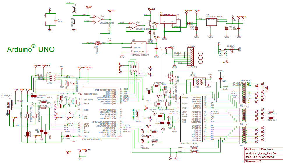
The schematic diagram is a pictorial representation of the wires and symbols of the circuit components. It is sometimes called wiring diagrams or circuit diagrams. It is used to show how the electrical or electronic circuit functions.
Tools
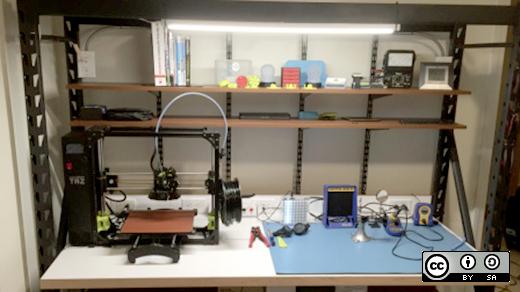
Before you start buying tools you will need to have a small workbench to build your electronic circuits.
Breadboard
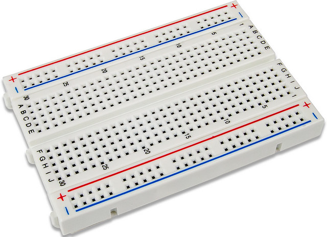
Breadboards used to prototype your circuits and test them before building them by soldering. Breadboards contain holes for inserting your components and also wires to interconnect the circuits.
Multimeter
A multimeter is an electronic device used to measure D.C and A.C electric current in Amps, the voltage in Volts, resistance in ohms, and some of them have the capability to measure capacitance and continuity. Watch this tutorial Baro Multimeter (Somali).
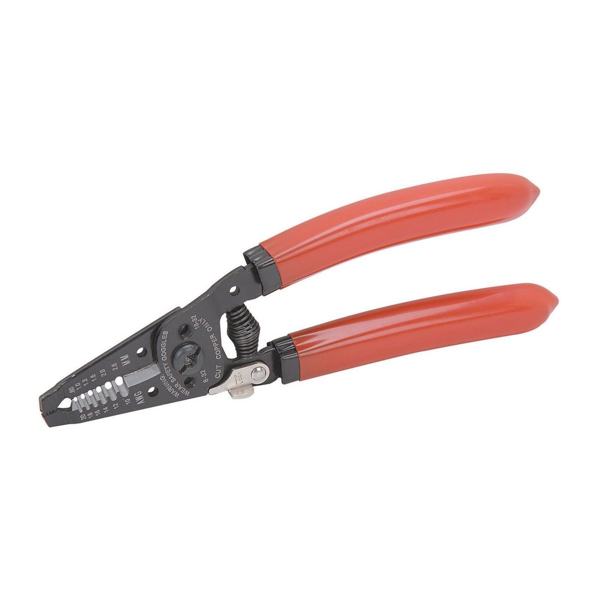
Wire Cutter and stripper
Wire strippers are used both to cut wires and also remove the insulation from electric wires in order to make contact.
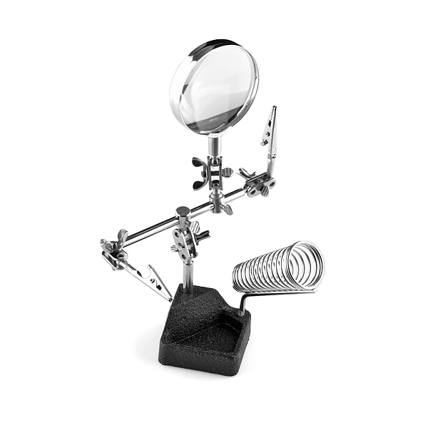
Helping Hand(3rd Hand)
Helping hand or 3rd hand is used when you are soldering, it is a very useful tool.
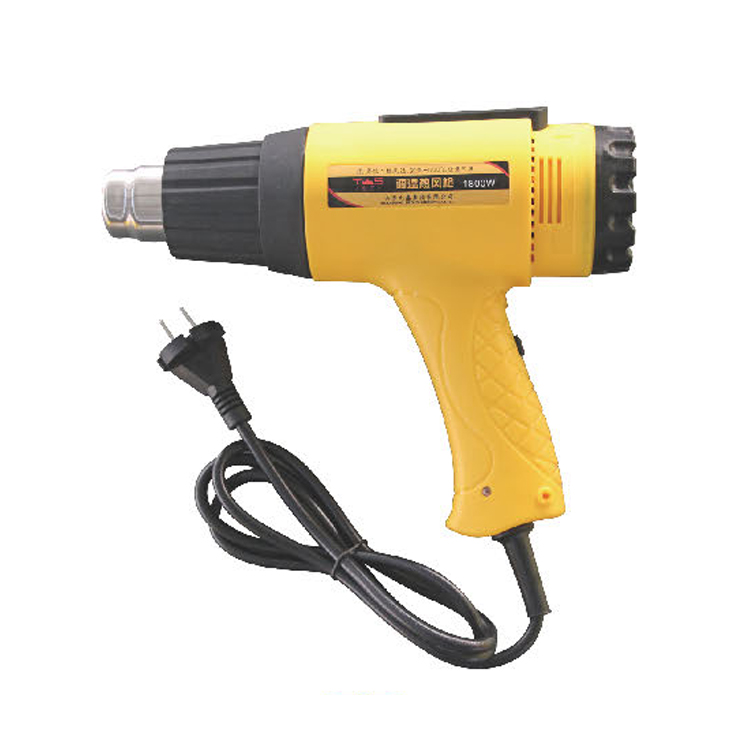
Heat Gun
A heat gun is used to shrink plastic tubing known as when you are using heat shrink to protect the wiring exposed.
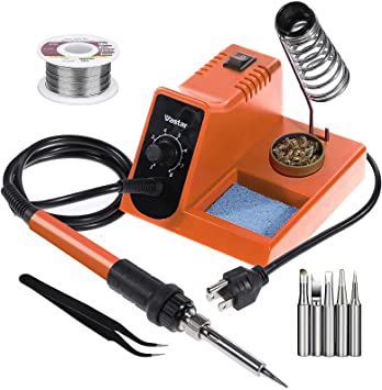
Soldering Iron
Soldering Iron is a hand tool that is used in soldering. Soldering iron provides the heat needed to melts the solder. Watch this Soldering Iron youtube tutorial Baro Soldering -Alxanka (Somali)
Conclusion
In this tutorial, I have just introduced you to a brief introduction of basic electronics knowledge and a review of many electronic components and tools you need to start your electronics training. To further increase your knowledge about electricity please watch my youtube channel. SomTronics


